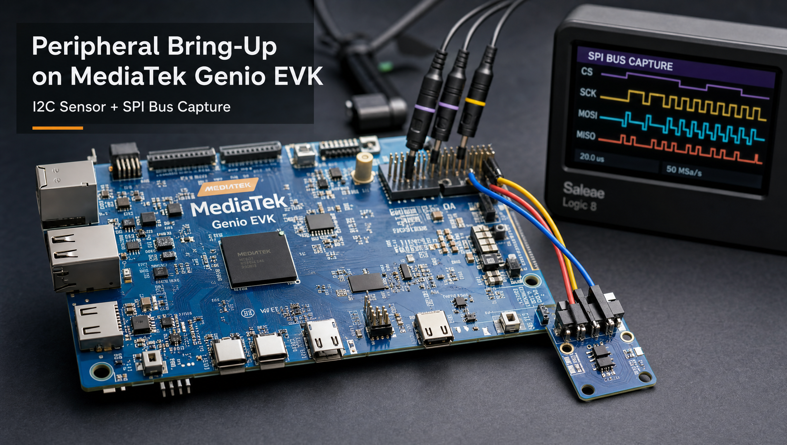
SPI and I2C peripheral setup on MediaTek Genio
SPI and I2C are the two most common buses for adding peripheral hardware to a Genio board: sensors, ADCs, display controllers, LoRa radios, and EEPROMs all use them. Both buses are exposed on the Raspberry Pi-compatible 40-pin HAT header on all Genio EVKs. Getting them working requires knowing the correct bus numbers, handling pin conflicts in the device tree, and verifying the connection before writing application code.
Key Insights
- I2C buses are numbered differently between Genio 510/700 and 520/720 EVKs: the HAT header is always I2C-0 on 520/720, and shared I2C-0 on 510/700
- SPI on 520/720 EVK requires a DTS patch: GPIO75 is shared with WiFi power enable; remapping to GPIO42 is mandatory before SPI1 works
- SPI loopback test requires a physical short between MOSI and MISO pins, without it,
spidev_testoutput looks like a failure i2cdetect -y <bus>is the fastest way to confirm an I2C device is wired and responding before touching application code/dev/spidev1.0is the standard spidev node for SPI1 on the 520/720 EVK after the DTS patch is applied
I2C setup and testing
List all I2C adapters
i2cdetect -l
On the Genio 520/720 EVK (9 I2C adapters total):
| Bus | Connected hardware |
|---|---|
| I2C-0 | Raspberry Pi HAT (SDA pin 3, SCL pin 5) |
| I2C-1 | Raspberry Pi HAT alternate (I2C-1 SDA/SCL) |
| I2C-2 | Current Monitor |
| I2C-4 | Charger IC, Buck regulator |
| I2C-5 | USB PD Controller |
| I2C-6 | Touch panel, SBU MUX |
| I2C-7 | CAM0 (CSI camera 0) |
| I2C-8 | CAM1 (CSI camera 1) |
On the Genio 510/700 EVK (7 I2C adapters):
| Bus | Connected hardware |
|---|---|
| I2C-0 | Touch CTP0 + Raspberry Pi HAT |
| I2C-1 | Charger IC, Buck IC, USB-C MUX |
| I2C-2 | Audio DTB + Raspberry Pi HAT |
| I2C-3 | Touch CTP1 + CSI1 |
| I2C-4 | USB PD Controller |
| I2C-5 | CSI0 |
| I2C-6 | CSI0 (additional) |
Scan a bus for devices
# Scan I2C bus 0, shows addresses as a hex grid
i2cdetect -y 0
Example output with a device at 0x48 (TMP102 temperature sensor):
     0  1  2  3  4  5  6  7  8  9  a  b  c  d  e  f
00:          -- -- -- -- -- -- -- -- -- -- -- -- --
10: -- -- -- -- -- -- -- -- -- -- -- -- -- -- -- --
...
40: -- -- -- -- -- -- -- -- 48 -- -- -- -- -- -- --
Read and write registers
# Read all registers of device at 0x48 on bus 0
i2cdump -y 0 0x48

# Read register 0x00 (temperature register on TMP102)
i2cget -f -y 0 0x48 0x00

# Write configuration to register 0x01
i2cset -f -y 0 0x48 0x01 0x60
The -f flag forces access even if the kernel driver has claimed the device. Use it cautiously in production, it bypasses the driver’s exclusive claim.
I2C in a Yocto image
The i2c-tools package provides i2cdetect, i2cget, i2cset, and i2cdump. Add to IMAGE_INSTALL:
IMAGE_INSTALL:append = " i2c-tools"
For kernel-level I2C access, ensure CONFIG_I2C_CHARDEV=y is set (it is in the default Genio kernel config).
SPI setup on Genio 520/720 EVK
The 520/720 EVK exposes SPI1 on the 40-pin HAT header. There is a pin conflict: GPIO75 is shared between SPI1 MOSI and the WiFi 3.3V power enable regulator. You must fix this in the device tree before SPI1 is usable.
HAT SPI pin mapping (520/720)
| Pin | Signal |
|---|---|
| 19 | SPI1 MOSI (GPIO75) |
| 21 | SPI1 MISO (GPIO76) |
| 23 | SPI1 SCLK (GPIO74) |
| 24 | SPI1 CS (GPIO73) |
DTS fix: remap WiFi power enable
File: arch/arm64/boot/dts/mediatek/mt8391-genio-720-evk.dts
Step 1: Move WiFi 3.3V enable from GPIO75 → GPIO42
pins_wcn_3v3_en: regulator-8 {
    regulator-name = "pins_wcn_3v3_en";
    regulator-min-microvolt = <3300000>;
    regulator-max-microvolt = <3300000>;
    gpio = <&pio 42 GPIO_ACTIVE_HIGH>;  /* was: 75 */
    enable-active-high;
    regulator-always-on;
};
Step 2: Update the pinctrl group to use GPIO42
pins-wifichip-wcn-3v3-en {
    gpio-hog;
    pinmux = <PINMUX_GPIO42__FUNC_GPIO42>,  /* was: GPIO75 */
             <PINMUX_GPIO79__FUNC_GPIO79>;
    output-high;
};
Step 3: Add SPI1 pingroup and enable the node
spi1_pins: spi1-pins {
    pins-spi-bus {
        pinmux = <PINMUX_GPIO73__FUNC_SPIM1_CSB>,
                 <PINMUX_GPIO74__FUNC_SPIM1_CLK>,
                 <PINMUX_GPIO75__FUNC_SPIM1_MO>;
        drive-strength = <MTK_DRIVE_6mA>;
        bias-disable;
    };
    pins-spi-mi {
        pinmux = <PINMUX_GPIO76__FUNC_SPIM1_MI>;
        bias-pull-down;
    };
};

&spi1 {
    pinctrl-0 = <&spi1_pins>;
    pinctrl-names = "default";
    #address-cells = <1>;
    #size-cells = <0>;
    status = "okay";

    spidev@0 {
        compatible = "mediatek,aiot-board";
        spi-max-frequency = <5000000>;
        reg = <0>;
    };
};
After applying and rebuilding, /dev/spidev1.0 appears on boot.
SPI testing
Critical first step: short MOSI (pin 19) to MISO (pin 21) on the HAT header. Without this physical loopback, RX data will not match TX and the test appears to fail.
# Load spidev module (should already be loaded)
modprobe spidev

# Verify device exists
ls /dev/spidev1.0

# Run loopback test at 400kHz
dd if=/dev/random of=test.bin bs=96 count=1
spidev_test -D /dev/spidev1.0 -s 400000 -i test.bin -v
Expected: TX and RX bytes match exactly. If they don’t, check the physical short between pins 19 and 21, and confirm the DTS patch is applied.
SPI setup on Genio 510/700 EVK
SPI-2 is exposed on the 40-pin HAT header. Unlike the 520/720, no WiFi pin conflict exists, but SPI-2 shares pins with CSI1 (camera 1).
Before enabling SPI-2: disconnect any CSI1 camera cable, then set jumpers:
| Jumper | Set to position | Signal |
|---|---|---|
| J4207 | 2-3 | SPI2 MOSI |
| J4208 | 2-3 | SPI2 MISO |
| J4209 | 2-3 | SPI2 CLK |
| J4215 | 2-3 | SPI2 CS |
After setting jumpers, the SPI device appears at /dev/spidev2.0.
Adding a real SPI device (example: MCP2515 CAN controller)
&spi1 {
    pinctrl-0 = <&spi1_pins>;
    pinctrl-names = "default";
    #address-cells = <1>;
    #size-cells = <0>;
    status = "okay";

    can0: mcp2515@0 {
        compatible = "microchip,mcp2515";
        reg = <0>;
        spi-max-frequency = <10000000>;
        clocks = <&mcp2515_osc>;
        interrupt-parent = <&pio>;
        interrupts = <110 IRQ_TYPE_EDGE_FALLING>;
    };
};

mcp2515_osc: mcp2515-oscillator {
    compatible = "fixed-clock";
    #clock-cells = <0>;
    clock-frequency = <16000000>;
};
Applying the DTS change in Yocto
Capture the change as a patch and apply it in your kernel bbappend, scoped to your specific machine:
# Generate patch from kernel source tree
git diff > mt8391-spi1-enable.patch
In your layer:
# recipes-kernel/linux/linux-mtk_%.bbappend
FILESEXTRAPATHS:prepend := "${THISDIR}/${PN}:"
SRC_URI:append:mt8391-genio-720-evk = " file://mt8391-spi1-enable.patch"
For custom carrier boards, author the SPI pinmux from scratch in your board DTS rather than patching the EVK DTS.
For device tree overlay patterns and the full Genio kernel bbappend workflow, see building a custom Yocto meta layer for Genio. For GMSL or MIPI camera bring-up on the same CSI connectors that share pins with these peripherals, see MIPI CSI camera driver setup on Genio.
FAQ
How do I detect I2C devices on MediaTek Genio?
Run i2cdetect -l to list all I2C adapters, then i2cdetect -y <bus> to scan a specific bus. On the Genio 520/720 EVK, I2C-0 is connected to the Raspberry Pi HAT header (SDA pin 3, SCL pin 5). On the Genio 510/700 EVK, I2C-0 is shared between Touch CTP0 and the Raspberry Pi HAT.
How do I enable SPI on the Genio 520/720 EVK?
GPIO75 is shared between SPI1 MOSI and the WiFi 3.3V power enable, you must remap the WiFi regulator from GPIO75 to GPIO42 in the DTS before SPI1 works. Without this DTS change, the WiFi module loses power when SPI is active.
What is the spidev_test command for verifying SPI on Genio?
Short MOSI (pin 19) to MISO (pin 21) on the HAT header first, then run: spidev_test -D /dev/spidev1.0 -s 400000 -v. TX and RX bytes should match exactly. Without the loopback short, RX data is garbage and the test appears to fail.
Does the Genio 510/700 EVK expose SPI on the Raspberry Pi HAT?
Yes, via SPI-2 on the 40-pin HAT header. SPI-2 pins are shared with CSI1, disconnect any CSI1 camera cable before using SPI-2. Set jumpers J4207-J4209 and J4215 to position 2-3 to route SPI to the HAT pins.
Relevant Services
MediaTek Genio Expert Support
Building on MediaTek Genio?
BSP bring-up, GStreamer pipelines, NeuroPilot integration, we've shipped it. Get unblocked fast. One call to scope it, fixed bid to deliver it.
Frequently Asked Questions
How do I detect I2C devices on MediaTek Genio?
Run 'i2cdetect -l' to list all I2C adapters, then 'i2cdetect -y <bus>' to scan a specific bus. On the Genio 520/720 EVK, I2C-0 is connected to the Raspberry Pi HAT header (SDA pin 3, SCL pin 5). On the Genio 510/700 EVK, I2C-0 is shared between Touch CTP0 and the Raspberry Pi HAT.
How do I enable SPI on the Genio 520/720 EVK?
The Genio 520/720 EVK exposes SPI1 on the Raspberry Pi HAT header (pins 19/21/23/24). GPIO75 is shared between SPI1 MOSI and the WiFi 3.3V power enable, you must remap the WiFi regulator from GPIO75 to GPIO42 in the DTS before SPI1 works. Without this DTS change, the WiFi module loses power when SPI is active.
What is the spidev_test command for verifying SPI on Genio?
Short MOSI (pin 19) to MISO (pin 21) on the HAT header first, then run: spidev_test -D /dev/spidev1.0 -s 400000 -v. TX and RX bytes should match exactly. Without the loopback short, RX data is garbage and the test appears to fail.
Does the Genio 510/700 EVK expose SPI on the Raspberry Pi HAT?
Yes, via SPI-2 on the 40-pin HAT header. However, SPI-2 pins are shared with CSI1 (the second camera connector). You must disconnect any CSI1 camera cable before using SPI-2. Set jumpers J4207-J4209 and J4215 to position 2-3 to route SPI to the HAT pins.

Written by
Aarón AnguloCo-Founder & CEO · ProventusNova
Obsessed with client outcomes. Aarón ensures every engagement delivers real results, on time, on scope, no exceptions.
Connect on LinkedInRelated Articles
Building a custom Yocto meta layer for MediaTek Genio
Create a custom Yocto meta layer for MediaTek Genio. layer.conf, kernel bbappend, DTS overlays, machine config, custom distro, and the RITY skeleton pattern.
MIPI CSI camera driver setup on MediaTek Genio
How to set up a MIPI CSI-2 camera on MediaTek Genio: device tree, sensor driver, seninf, V4L2 pipeline, and capturing frames with GStreamer.
Jailhouse hypervisor on MediaTek Genio: bare-metal isolation on Linux
Jailhouse hypervisor on MediaTek Genio 720: cell config, GIC addresses, required kernel patches, MTK vendor config, and IVSHMEM communication.
ISP differences between Genio 510/700 and Genio 520/720
What changed in the MediaTek Genio ISP between Gen 1 (510/700) and Gen 2 (520/720): pipeline depth, virtual channels, and camera driver differences.